




What components make up a copper manifold system?
 Nov 09, 2025|
The copper manifold system serves as the core distribution unit in radiant floor heating (hydronic floor heating) or cooling systems. It efficiently distributes hot or cold water from the heat source (such as a wall-mounted boiler or heat pump) to individual heating/cooling circuits while collecting return water to feed back to the heat source.
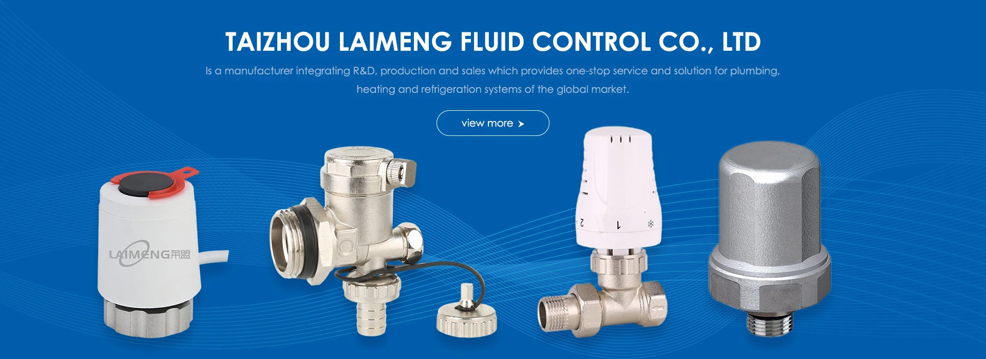
A complete copper manifold system primarily consists of the following core components:
I. Core Main Components
Manifold Main Pipe
Function: Connects to the system's main supply pipe, distributing hot/cold water to individual branches.
Features: Typically includes a valve at each outlet to control flow to that branch.
Manifold Collector Pipe
Function: Connects to the system's main return pipe, gathering low-temperature/high-temperature water circulating back from branches and returning it to the heat source for reheating/recooling.
Characteristics: Each return port is usually equipped with a valve.
Supply/Return Connectors
Function: Connect the main supply and return manifolds, typically via T- or U-shaped copper castings. Pre-drilled ports accommodate automatic air vents and drain valves.
II. Control and Regulation Components
Ball Valves or Globe Valves
Location: Installed at the manifold's supply inlet and return outlet.
Function: Serves as the system master switch to open or close water flow throughout the manifold system, facilitating maintenance and repairs.
Regulating Valve (Manual or Automatic)
Location: Installed at the outlet of each branch circuit on the manifold.
Function:
Manual Regulating Valve: Manually adjusts flow rate by rotating the valve core to control flow in the branch circuit, achieving temperature balance across different rooms.
Automatic Control Valve (Flow Meter): Features a transparent window and scale for visual monitoring and precise adjustment of flow in each loop, ensuring optimal hydraulic balance and system performance.
Electric Actuator
Location: Installed on the control valve of each manifold branch.
Function: Receives electrical signals from room thermostats to drive valve opening/closing, enabling automatic temperature control for each room or zone.
Automatic Air Vent
Location: Installed at the top of supply and return pipe connections.
Function: Automatically expels air generated within the piping system, preventing air locks to ensure unobstructed water flow and efficient system operation.
Drain Valve (Drain Plug)
Location: Installed at the bottom of supply and return pipe connections.
Function: Used to drain water from the manifold and piping during system maintenance, cleaning, or freeze protection.

III. Accessories and Supporting Components
Pressure Gauge and Thermometer
Function: Monitors real-time system operating pressure and supply/return water temperatures, enabling users or technicians to assess system status.
Mounting Bracket
Function: Securely anchors the entire manifold system to walls or installation enclosures.
Insulation Sleeve
Function: Fits over the manifold's main pipe to prevent surface temperatures from becoming excessively high (causing heat loss) or low (preventing condensation during cooling mode).
Thermostatic Control Unit (Optional but Critical)
This integrated device combines circulation pumps, temperature sensors, control valves, and more, typically installed between the wall-mounted boiler and manifold. It automatically adjusts pump speed and mixed water temperature based on system demand, serving as a key component for enhancing comfort and energy efficiency.

IV. System Synergy Components
Though not directly mounted on the manifold, these are integral to the manifold system:
Circulation Pump: Provides the driving force for water circulation.
Room Thermostat: Sends control signals to the electric actuator.
Underfloor Heating Pipes: Connect the terminal piping of each branch from the manifold.
Summary
A typical copper manifold system constitutes a precision module comprising the "manifold body + control valves + electric actuators + air vent and drain device + monitoring instruments." Its design and configuration directly determine whether the underfloor heating system can achieve room-by-room temperature control, hydraulic balance, and efficient energy-saving operation.